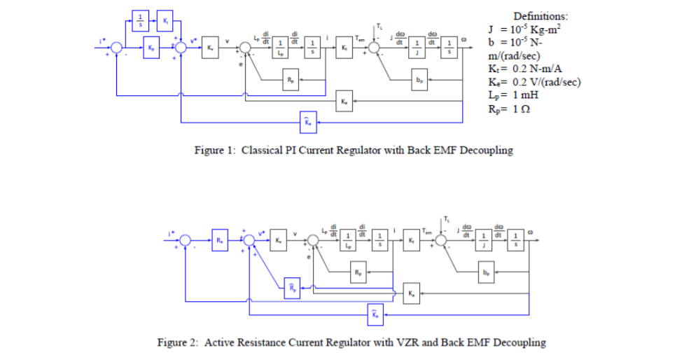
You are the controls engineer for XYZ Company and your boss has asked you to analyze and “tune” a current controller for a DC motor drive system. Not having a lot of experience tuning current regulators, you decide to systematically analyze the system and simulate its dynamic response. You decide to try two different methods:
1. Classical proportional plus integral (PI) control
2. A proportional controller using Active Resistance and a virtual zero reference (VZR) decoupling technique
You’ll try both of these with and without back EMF decoupling to explore the differences.

To do:
a) Develop the current regulator transfer function with a proportional plus integral controller without back emf decoupling Tune the value of Kp and Ki to yield a 1000 Hz bandwidth at locked rotor (zero speed)
b) Develop the current regulator transfer function with a proportional plus integral controller with back EMF decouplmg Do not assume that die estimate of back emf exactly cancels the physical back EMF (retain both terms in the transfer function)
c) Develop the current regulator transfer function with active resistance with VZR decoupling.
Do not assume that the estimated value of Rp exactly cancels the physical resistance (retain both resistance terms m the transfer function). Tune the value of R* to yield a 1000 Hz bandwidth at locked rotor (zero speed)
d. Develop the current regulator transfer function with active resistance with VZR and back EMF decoupling Do not assume that the estimated value of Rp exactly cancels the physical resistance or that the estimate of back EMF exactly cancels the physical back EMF (retain both resistance terms and both back EMF terms m the transfer function).
e Evaluate the frequency response of the current regulator for parts ‘a’ and ‘o’ at zero speed For part c\ test the effects of estimation error with the VZR. Assume the estimated value of resistance is incorrect by +/- 20%.
f. Evaluate the frequency response of the current regulator for parts ‘b’ and d’ at zero speed and at nonzero speed assuming the back EMF estimate is accurate. Next test effects of estimation error. Assume back EMF estimate is incorrect by +/-10%. For part ‘d\ assume the estimated value of resistance is incorrect by +/- 20%. Test the response with the estimated back EMF set to zero to see how die system responds at nonzero speed without decoupling
g. Given a current command of i*(t) = Iosin(2jt£t) where Io = 5A and £ = 1. 10. and 100 Hz. plot die command and response of the current regulator as functions of tune
h. Simulate the system using the gams calculated from above (can use Simulink or other programs if desired) Explore the response of both current regulators to varying conditions and discuss findings.
i. Provide a highly organized report with very clear figures and equations The report should detail the design and analysis of the current regulator and list observations
Hand in:
1 A derivation of the transfer functions for pan ‘a* through d\
- Frequency response plots of the current regulator with and without back EMF decoupling at zero speed and nonzero speed.
Calculate
r
for each of the cases listed above
Superimpose the results for all of the cases on on FRF plot.
Amplitude (in dB) vs log frequency (standard FRF format)
Include your program listing with sufficient comments/text to allow reasonable review
- Time domain plots of commanded current and output current Superimpose both commanded and output current with and without back EMF decoupling on same plot for each of the commanded frequencies (1, 10. and 100 Hz).
4 Appropriately detailed discussion of important results and comparative findings Discuss where the analytical results deviate from the simulation results


Recent Comments